(Note (X-Y) refers to location Row-Column silkscreened on board)
The Apple 1 is pretty easy to construct. All the part names are silk-screened directly on the printed circuit board. For the most part, just stuff the board with components and solder, apply a few jumpers, hook up the keyboard, monitor and transformers and away you go. Here are a few tips.
1. First verify the kit is not missing any parts. A part list is included, although every attempt was made to ensure all parts were included, sometimes mistakes are made, please email obtronix@yahoo.com for quick replacements.
2. Begin by installing and soldering all IC sockets (if used, IC sockets are not included in some kits kit), the two Molex type connectors (the white ones ) and expansion connector (the big green one).
3. Install LM-323 (D-18) regulator and heatsink. First screw LM-323 + thermal pad(clear plastic included in mounting kit) and heatsink to board, then solder leads. Do not use the nut insulators included in the mounting kit, as the case of the LM-323 must be grounded to the board ground for the power supply to work.
4. Install three TO-220 regulators (D-16), looking at the board face on, the first regulator, positive 12V, is installed with the part number printing facing you, the second two regulators, negative 12 and 5, are installed backwards, with the part number printing facing toward the back of the board.
5. Solder all resistors, caps, diodes and crystal. Part values and orientation guides are silkscreened on the board. The 1uF silkscreened parts # are actually installed with .1uF caps, as on the original Apple computer.
6. Install Spectrol 100 ohm trim pot (D-1), there are three pins on this part, install with the middle pin facing away from you.
7. Install Motorola 3704 transistor (D-1) , follow the orientation silkscreened on the board.
8. If using sockets, install the chips, otherwise solder all chips to the board.
9. Check the board for empty parts, all parts should now be installed.
10. Short option jumpers with a big glob of solder or a small bare piece of wire
* Short two 6502 jumpers (A-5,A-8)
* Short No DMA jumper (A-9)
11. Short Memory map jumpers (B-9,B-10). The below options are the most popular and enables you to use Apple 1 basic and the cassette interface. Use a small thin wire with insulation, otherwise they will short out.
* Short Y to F, Z to D, R to C, W to E and X to 0
12. Mount Board on plywood using 5 standoffs (one in each corner and in the middle of the board)
13. Your Apple 1 motherboard is complete. Hook up the keyboard, power, clear screen and reset switches, and monitor per the schematics.
14. Power up tips
* After powering up you will need to trim the 100 ohm trim pot to obtain a clear image on the screen.
* The Apple has no power on reset circuitry, in that it doesn't come up running, first push the clear screen button and then the reset key, a cursor should now appear.
15. Debug hints, if the Apple is not working check the following
* First check the power rails for proper voltage
* Check clock input
* Check to make sure there are no solder bridges
* If using sockets make sure all pins are firmly in the socket.
* If the Apple is up and running but it is not responding correctly to monitor commands, it most likely is a bad DRAM chip or DRAM chip connection, try swapping the X DRAMS with the Y DRAMS, the monitor code uses the X DRAMS only.
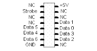
* If a Keyboard is included in the kit, the pinout is (note remove conductive tape from back of keyboard before powering up)

No comments:
Post a Comment