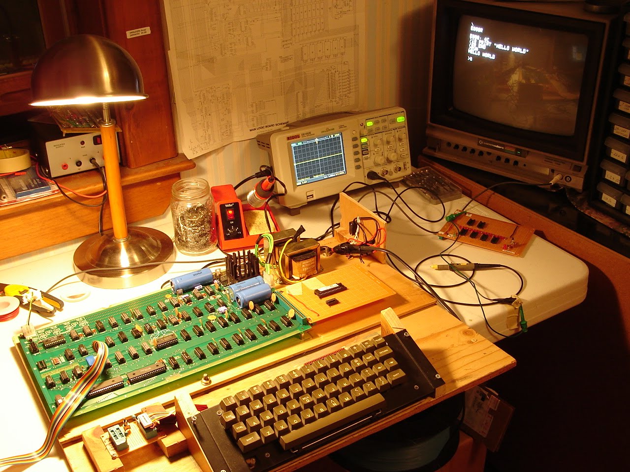
The DRAM chips are MOSTEK 4027 P-3, most made in the 14th, and 19th weeks of 1976. The Motorola 6820L was made in the 48th week of 1976. Note the gold grounding straps on some of the DRAM chips.
Saturday, June 26, 2010
Gold Purple Ceramic chips from 1976
Friday, June 18, 2010
Wednesday, June 2, 2010
Hand Wired / Wire wrapped Apple-1 = WOW
Monday, May 31, 2010
A1-Mimeo clone up and running (BASIC)
This all started when I could not read the data I had just deposited into memory anywhere in Bank X. Mike had me test using 0 and FF at different memory locations, for example:
0:FF (deposit FF at mem location 0000)
0:0 (deposit 0 at mem location 0000)
1000:FF (deposit FF at mem location 1000)
1000:0 (deposit 0 at mem location 1000)
After doing the deposit, we checked the data with a read:
1000.1000
Output: 1F
What we were seeing was 5 bits that were"stuck" 0001 1 1 1 1
(wrong, this should have been 0 or 0000 0000 )
The next thing we did was swap the chip select jumpers:
Before:
W=>1
X=>0
After:
W=>0
X=> 1
Normally, the PROM monitor will use the X bank, so what we did here was to use the W bank of RAM instead. I switched the jumpers, and ran the tests again. Bank W was working correctly.
So this was a pretty good indicator that the problem was somewhere in the X bank and not somewhere else on the board. At this point, we started probing the ground and power pins at each X bank DRAM chip. I checked +5v (pin 9), +12v (pin 8) and lastly -5v (pin 1) until we found the problem.
UPDATE (June 18, 2010): Here is a test program Mike had me use for testing the RAM -
0: AD 00 10 4C 00 00
This HEX code is : LDA 1000 with a Jump back to 0
That will loop forever and generate an alternating square wave (toggling) on the oscillocope at pins 1 and 2
Tuesday, May 25, 2010
A1-Mimeo (Apple-1 clone) stuffed - first power up test
Initial Power applied to the A1-Mimeo before stuffing the board
If you're wondering about the power supply and how to build it, please see my earlier posts when I built the first clone. I am using the same power suppy here to test the Mimeo-1. Before stuffing the board I checked each voltage source and ground at each DIP. I checked the big blue caps as well. Everything looks good. In this image, I have the scope set for 5 volts per div. The card you see hanging off of the PCB is a card that I built for address line display (the red leds) and correct +5v regulated power at the J3 connector. The card also has a reset button that can be used when no keyboard is attached. The little green LED is lit, we are good to go.
Monday, May 24, 2010
Chip Select Jumper Configuration
W might normally be connected to E so that memory bank W is available for the Cassette Interface Adapter (e.g. to load BASIC from tape into bank W). I have a different configuration: W=>1 and S=>E, so that I can use my BASIC firmware card instead of loading from tape.
Note that S, T and R are "user selectable" chip selects, of 4k each. In my configuration, S is used as the chip select for the BASIC firmware card.
Saturday, May 22, 2010
Friday, May 21, 2010
A1-Mimeo DIP sockets completed by 2:30 AM
Tuesday, May 18, 2010
Datanetics Keyboard Disassembled
Sunday, May 16, 2010
Saturday, May 15, 2010
White Stickers


Have you ever noticed that some of the original Apple-1 units have a small white sticker on the back? I have never seen a number greater than 82. Recall that 200 units were manufactured.
Yesterday I asked Steve Wozniak if these stickers represent the serial number of each board. Unfortunately, Woz does not remember.
So I sent an email to Steve Jobs today asking him... he responded from his iPhone and said:
"It was not put on by us."
Steve
Steve
So what is the true meaning of these little white stickers?
Apple-1 Registry
Mike Willegal is putting together a registry of existing (allegedly), Apple-1 originals. If you have any information on any of the units Mike has documented, or know of any other Apple-1 boards not listed, please contact Mike, or post a comment here.
Friday, May 14, 2010
Wendell Sander's Apple-1 Website
I've been meaning to post this link provided by Wendell Sander -- it is a work in progress. There are source files for Apple-1 programs, and other info, so check it out.
Monday, May 10, 2010
Apple-1 BASIC Firmware Card... it works.
See the video of the card up and running Hello World!

I used a 512k EPROM because it's all I had on hand. BASIC is only 4k so you can use a much smaller chip if you'd like. (I have some 8k chips ordered...) I programmed the AT27C040 EPROM using a "Top2004" programmer.
Note that on the Apple-1, I have jumpered "S" to "E" (CSE) so that when E000R is entered, BASIC will run.
This is the apple1basic.bin file, which I downloaded many months ago from www.pagetable.com. This is the same output I was seeing with my BASIC firmware card. (At this point, you must do a reset, as BASIC fails to load).
I then loaded the "basic.rom" file that is included with Pom1 and it loaded BASIC without any problem. Clearly something wasn't right here... so I did a cmp/diff on the two files, and as it turns out, 2 bytes are incorrect in the apple1basic.bin file downloaded from www.pagetable.com.
see below, where hilited - (decimal 976 and hex 03D0):

The above 2 images show the hex and decimal locations of the 2 incorrect bytes found in apple1basic.bin
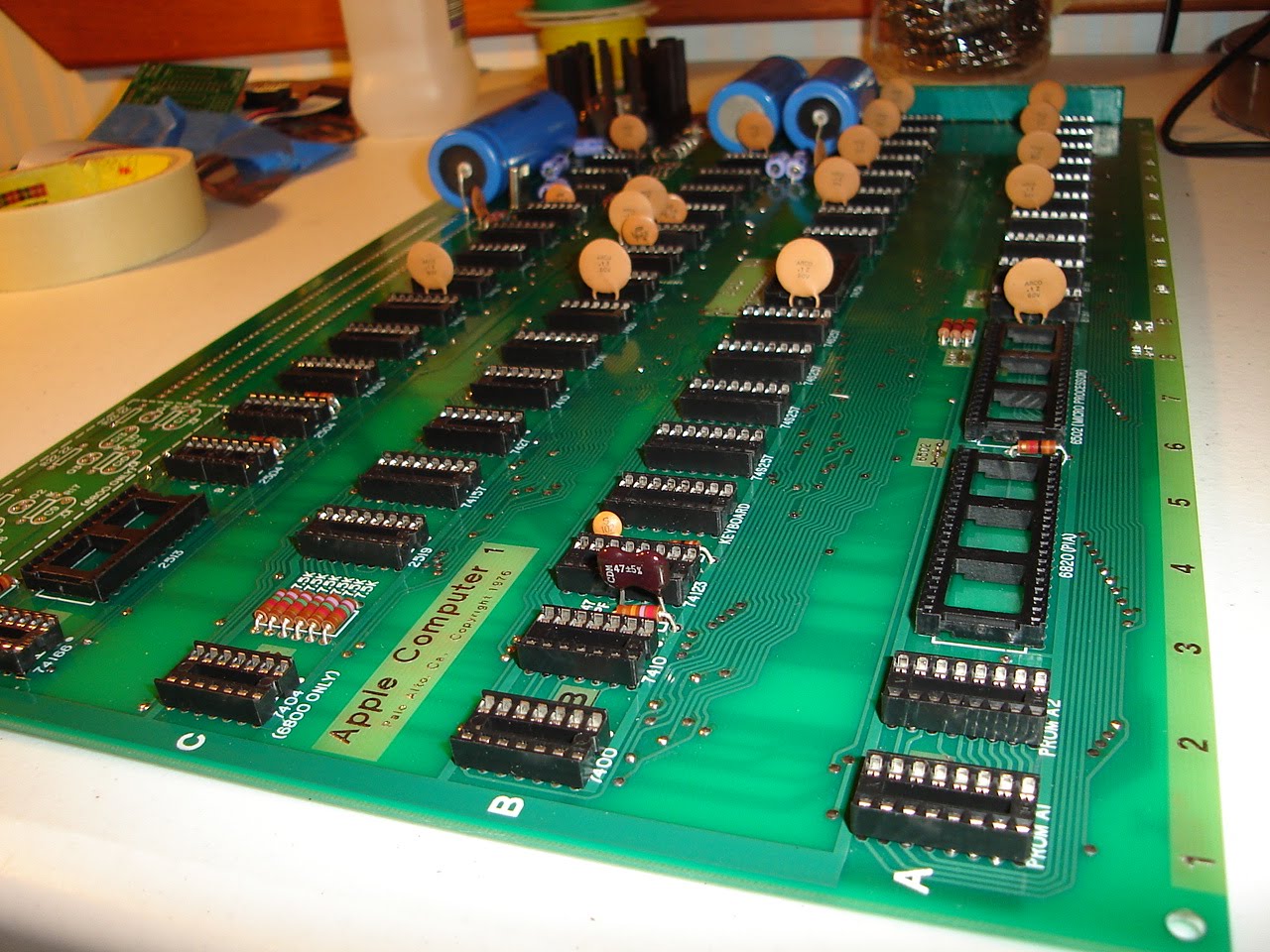
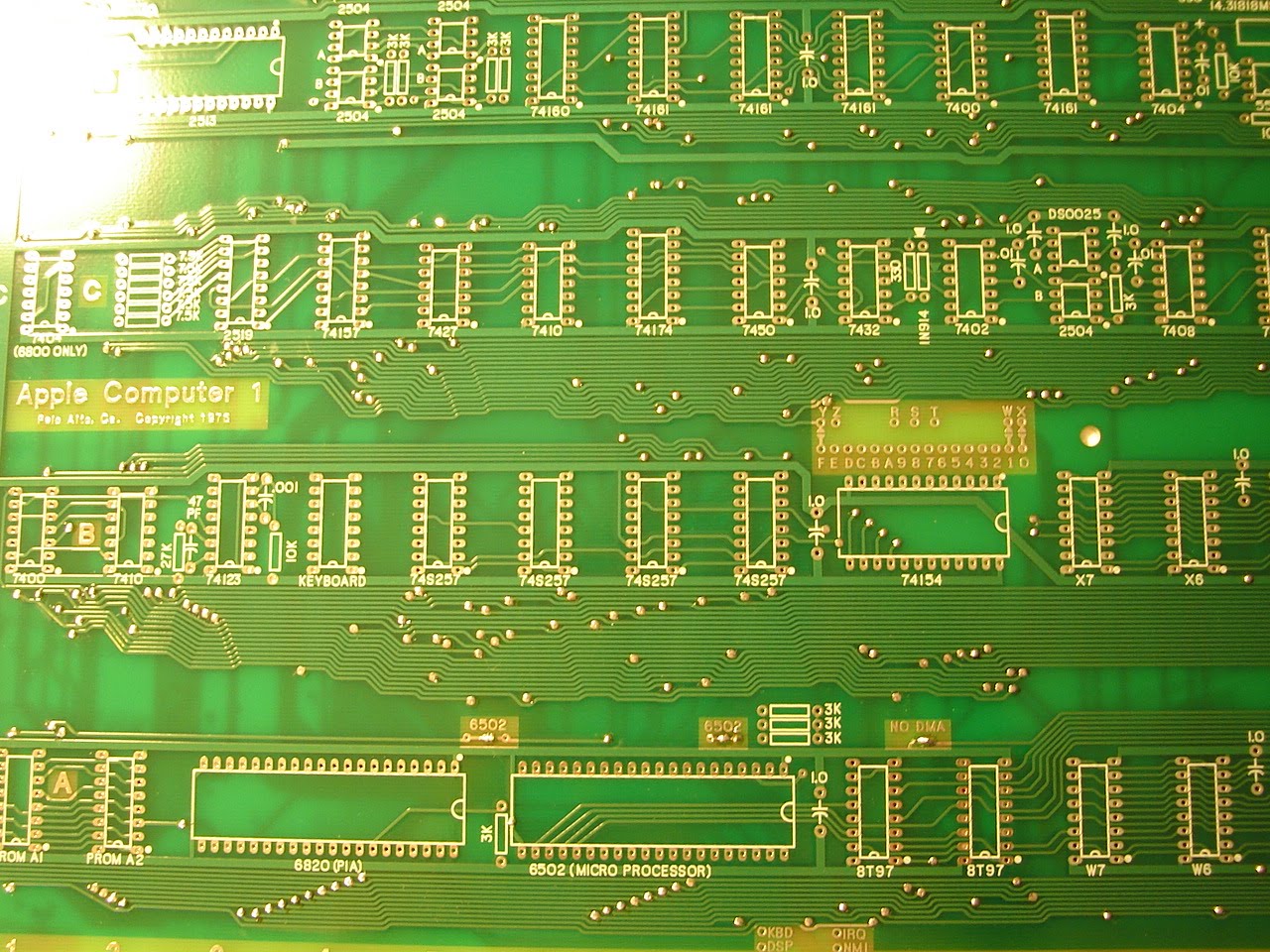
In addition to the ROM file differences, I found I had my wires crossed.... the above image shows the incorrect wiring on address lines A8, A9 and A11.
After moving these address lines to their correct locations, and burning the EPROM with the new working BASIC ROM file, you can see that I was able to load and run the BASIC "Hello World!" program.
UPDATE: September 22, 2010 - Here is a link to the Basic Disassembly
Download the files, and view with a text editor.
Subscribe to:
Posts (Atom)


